


How Does Truck Chassis Selection Affect Knuckle Boom Crane Stability and Mobility?
Views: 134 Author: Site Editor Publish Time: 2026-08-31 Origin: Site


In heavy lifting operations, the truck chassis serves as far more than a simple transportation method. It acts as the primary counterweight and the foundational structural anchor for the entire lifting process. When operators deploy a crane, the vehicle frame absorbs massive torsional forces and dynamic weight shifts. If the chassis lacks the necessary rigidity or mass, the entire system becomes compromised, regardless of the crane's standalone capabilities.
Mismatching equipment introduces severe operational and financial risks. An undersized or improperly configured chassis restricts the load chart, introduces dangerous tipping hazards, and limits job site access. Fleet managers often find that a poorly specified truck effectively neutralizes their investment, rendering the equipment unsafe or incapable of performing its intended tasks. The balance between lifting power and vehicle stability dictates the success of daily operations.
To ensure maximum operational efficiency and safety, professionals rely on a strict technical evaluation framework. This process aligns crane lifting moments—measured in ton-meters—with specific chassis specifications, including Gross Vehicle Weight Rating (GVWR), axle spacing, and frame yield strength. Understanding this relationship allows operators to maximize payload capacity while maintaining the structural integrity required for complex, heavy-duty lifts.
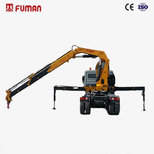
Load Distribution is Non-Negotiable: The placement of a truck mounted knuckle boom crane (behind-the-cab vs. rear-mount) fundamentally alters the center of gravity and dictates required axle ratings.
Frame Strength Precedes Lift Capacity: A folding boom crane can only lift what the chassis frame's Section Modulus and Resistance to Bending Moment (RBM) can support without permanent deformation.
Rotational Stability Requires Rigidity: Dynamic slewing and 360-degree rotation mechanics introduce torsional forces that demand a matching subframe and rigid chassis construction.
Mobility vs. Stability Trade-off: Longer wheelbases and multiple axles increase stability and payload capacity but compromise turning radius and urban job site accessibility.
Regulatory Compliance: Proper chassis selection prevents costly overweight fines and ensures compliance with local bridge laws and axle weight restrictions.
The Physics of Stability: Why the Chassis Matters for a Knuckle Boom Crane
Center of Gravity (CoG) Dynamics
The articulating nature of a knuckle boom crane shifts the center of gravity dynamically during every phase of a lift. Unlike static loads, a suspended load moving through multiple articulation points creates variable torsional stress across the vehicle frame. As the boom extends horizontally, the leverage exerted on the chassis multiplies. The truck frame must possess the structural density to absorb these shifting forces without twisting or lifting off the ground. A properly specified chassis acts as an anchor, keeping the combined center of gravity safely within the vehicle's footprint. When you extend the boom fully, the center of gravity moves away from the truck centerline. This shift demands a chassis heavy enough to counteract the tipping moment. Operators must understand that the truck's mass is the primary defense against overturning.
Rotation Mechanics and Slew Stability
Slewing, or rotating the crane, drastically alters the stability profile of the vehicle. Lifting zones are generally categorized into over-the-cab, over-the-side, and over-the-rear operations. Each zone presents unique stability challenges. Over-the-side lifts rely heavily on the outrigger spread and the torsional rigidity of the chassis rails. Over-the-cab lifts are often the most restricted due to the lighter weight of the front axle and suspension limitations. The overall width and weight of the chassis directly dictate the allowable lift capacity in each specific zone, requiring operators to constantly reference zone-specific load charts. You cannot assume uniform capacity across a 360-degree rotation. The chassis configuration dictates the safe working load in every quadrant.
Lifting Zone | Stability Factor | Primary Chassis Dependency | Typical Capacity Restriction |
|---|---|---|---|
Over-the-Rear | High | Rear axle weight and frame extension | Minimal restriction (often 100% chart) |
Over-the-Side | Medium | Outrigger stance and torsional rigidity | Moderate restriction based on outrigger spread |
Over-the-Cab | Low | Front axle weight rating (FAWR) | High restriction (often 50% or less of max capacity) |
Side-Loading Resilience
A knuckle boom design is inherently rugged, capable of handling significant side-loading forces compared to traditional stiff or telescopic booms. When operators manipulate bulky or asymmetrical loads, lateral forces transfer directly down the pedestal and into the truck's chassis frame. The articulating arms allow for precise load placement, but this precision often generates lateral stress. The chassis and subframe must be engineered to resist this side-loading, preventing frame warping and ensuring the crane maintains its structural alignment over years of heavy use. Side-loading occurs frequently when dragging loads or operating in high winds. The truck frame must resist these lateral forces without permanent deflection.
Gross Vehicle Weight Rating (GVWR) vs. Usable Payload
Calculating usable payload requires subtracting the weight of all installed equipment from the truck's GVWR. Once you install the crane, the heavy-duty subframe, hydraulic outriggers, and the flatbed body, the remaining weight allowance represents your actual payload capacity. Failing to account for the substantial weight of the crane components leads to overloaded axles and severe regulatory penalties. Operators must balance the desire for a high-capacity crane with the practical need to transport materials to the job site legally. A heavier crane eats directly into your legal payload. You must calculate this trade-off before purchasing the chassis.
Counterweight Mechanics
In mobile crane operations, the chassis mass functions as the primary counterweight. Relying solely on outriggers without adequate vehicle weight leads to immediate instability, especially at maximum horizontal reach. Outriggers widen the stance and provide leveling, but they do not add mass. The engine, transmission, axles, and frame rails provide the necessary gravitational anchor to offset the leverage of a fully extended boom. A lightweight chassis paired with a high-capacity crane will tip long before the crane reaches its structural lifting limit. You need iron on the ground to keep the rubber on the road.
Mounting Positions on a Truck Mounted Knuckle Boom Crane
Behind-the-Cab Mounting (Standard Configuration)
Mounting a truck mounted knuckle boom crane directly behind the cab remains the most common configuration in the industry. This setup keeps the center of gravity forward, which improves steering axle traction and driving dynamics. It also maximizes the continuous rear deck space available for hauling materials. However, this position places immense stress on the front axle. If the crane is excessively heavy, it can easily overload the Front Axle Weight Rating (FAWR), leading to premature tire wear and compromised steering control. You must specify a heavy-duty front axle for this setup.
Rear-Mount Configurations
Rear-mounted setups are highly effective for operators who frequently lift heavy materials directly off the rear of the truck or an attached trailer. This configuration excels in below-ground-level operations, such as placing utility vaults, setting septic tanks, or handling heavy foundation forms. By positioning the crane at the rear, operators gain unobstructed reach behind the vehicle. The primary limitation is weight distribution; a heavy rear-mount shifts significant mass behind the rear axles. This can cause front-axle lift, reducing steering effectiveness and requiring specific tandem or tridem axle setups to maintain safe drivability.
Center-Mount Configurations
A center-mount configuration places the crane in the middle of the flatbed. This approach balances weight distribution evenly across all axles, mitigating the risks of overloading either the front or rear suspension. It provides excellent all-around stability for 360-degree lifting. The distinct disadvantage is that it splits the payload area into two smaller sections. This severely limits the length of materials that the truck can transport, making it unsuitable for hauling long pipes, lumber, or steel beams. Center mounts work best for specialized utility trucks that do not haul long freight.
Operational Ergonomics: Curb-Side vs. Street-Side Layouts
The layout of the crane controls directly impacts operator safety and visibility. Manual control consoles must be positioned to keep the operator out of active traffic lanes during roadside lifts. Curb-side controls are generally preferred for municipal and utility work. However, the adoption of radio remote controls has transformed operational ergonomics. Remotes allow the operator to move freely, maintaining clear sightlines of the load, the boom tip, and the surrounding environment, regardless of where the crane is mounted on the chassis. Remote controls eliminate the need to stand near the pedestal, keeping operators out of the danger zone.
Axle Configurations and Payload Trade-offs
Single vs. Tandem vs. Tridem Axles
Selecting the correct axle count is a direct function of the crane's ton-meter rating and the required daily payload. Single axle trucks offer excellent maneuverability but are limited to smaller cranes and lighter payloads. Tandem axles provide the necessary weight capacity for mid-to-large cranes while maintaining reasonable turning radiuses. Tridem setups are reserved for the heaviest lifting applications, offering maximum payload and stability, though they sacrifice significant maneuverability on tight job sites. You must match the axle count to the heaviest load you plan to haul legally.
Axle Configuration | Ideal Crane Size | Payload Capacity | Maneuverability |
|---|---|---|---|
Single Axle | Light (up to 10 ton-meter) | Low | High (Tight urban access) |
Tandem Axle | Medium (10 to 30 ton-meter) | Moderate to High | Moderate |
Tridem Axle | Heavy (30+ ton-meter) | Maximum | Low (Requires wide clearance) |
Front Axle Weight Ratings (FAWR) and Steering Impact
The FAWR dictates how much weight the front steering axle can legally and safely support. Overloading the front axle—often caused by a heavy behind-the-cab crane—creates dangerous driving conditions. It leads to accelerated tire wear, heavily compromised braking distances, and stiff, unresponsive steering. Operators must ensure the chassis features a front axle rated appropriately for the specific crane model, often requiring upgrades to 18,000 or 20,000-pound front axles for larger units. A weak front axle will fail under the dynamic bouncing of a heavy crane during highway transit.
Pusher and Tag Axles
To navigate strict highway weight regulations without permanently sacrificing maneuverability, fleet managers often specify auxiliary lift axles. Pusher axles (located ahead of the drive axles) and tag axles (located behind) can be lowered to distribute weight over a larger footprint, satisfying bridge formulas. Once on a tight job site, the operator can raise these axles to shorten the effective wheelbase, allowing the truck to navigate narrow residential streets or congested construction zones. Lift axles provide the best of both worlds: legal highway weight and job site agility.
Frame Specifications: The Backbone of a Folding Boom Crane
Section Modulus and Yield Strength
The structural integrity of a truck frame is defined by two primary engineering metrics: Section Modulus and Yield Strength. Section Modulus measures the physical shape and size of the frame rail, while Yield Strength measures the quality and tensile strength of the steel. Multiplying these two figures provides the Resistance to Bending Moment (RBM). The RBM is the ultimate indicator of a frame's ability to withstand the immense leverage applied by a folding boom crane. If the crane's lifting moment exceeds the chassis RBM, the frame will permanently bend or crack. You cannot compromise on RBM. It is the mathematical limit of your truck's structural strength.
The Role of the Subframe
A folding boom crane is rarely, if ever, mounted directly to the bare truck frame. Direct mounting creates severe localized stress points that lead to catastrophic frame failure. Instead, upfitters engineer a heavy-duty steel subframe that sits between the crane base and the truck chassis. This subframe absorbs the concentrated forces generated during a lift and distributes them evenly across the entire length of the chassis rails. The subframe also houses the outrigger cross-tubes, tying the stabilization system directly into the lifting structure. The subframe acts as a structural bridge, protecting the truck's factory frame from point-loading.
Torsional Rigidity
While RBM addresses vertical bending, torsional rigidity addresses the frame's ability to resist twisting. When a crane handles bulky, unbalanced loads at a 90-degree angle to the truck centerline, it applies massive rotational force to the chassis. A frame lacking torsional rigidity will twist, causing the outriggers to lift and destabilizing the entire platform. Boxed subframes and reinforced cross-members are utilized to stiffen the chassis, ensuring it remains flat and stable during aggressive side-loading operations. A twisting frame is a dangerous frame. Rigidity keeps the outriggers planted firmly on the ground.
Mobility Factors: Navigating Public Roads and Job Sites
Highway Transport vs. Mobile Crane Logistics
One of the primary advantages of this equipment is roadability. Unlike dedicated mobile cranes that often require special transport permits, pilot cars, and restricted routing, a properly specified commercial truck chassis can travel at standard highway speeds. This allows operators to mobilize quickly, complete a lift, and move to the next site within hours. The logistics are simplified, reducing overhead costs and eliminating the need for separate transport trailers. You drive to the site, set up in minutes, complete the lift, and drive away.
Turning Radius and Wheelbase Considerations
There is a strict inverse relationship between a long, stable wheelbase and the ability to navigate confined spaces. A longer wheelbase provides a larger footprint, increasing lifting stability and allowing for longer payload beds. However, it drastically increases the vehicle's turning radius. Fleet managers must evaluate typical job site conditions. If the truck frequently operates in narrow urban alleys or tight residential developments, a shorter wheelbase is mandatory, even if it requires scaling down the crane capacity. You must measure the physical constraints of your typical job sites before ordering a chassis.
Off-Road Capabilities and Frame Torsion
For off-highway applications like forestry, pipeline construction, or powerline maintenance, the chassis requirements change significantly. Ground clearance, aggressive tire treads, and locking differentials become necessary. Furthermore, the frame must possess a degree of engineered flexibility. A completely rigid frame on uneven terrain will cause tires to lift off the ground, resulting in a loss of traction. The subframe mounting system must allow the truck chassis to flex naturally over ruts and rocks while keeping the crane base secure. Off-road trucks need frames that can breathe and flex without breaking.
Wind Loading and Environmental Factors
Environmental conditions, particularly wind, play a major role in mobility and stability. Wind loading exerts lateral pressure on both the boom structure and the suspended load. Large, flat-sided materials like drywall bunks or roofing panels act as sails. A heavier chassis with a wide outrigger stance provides the necessary mass to resist these destabilizing wind forces. Operators must reduce load capacities in high winds, relying on the solid footprint of the truck to maintain a safe center of gravity. Wind can turn a safe lift into a rollover in seconds. The truck's mass is your primary defense against wind gusts.
Evaluating the Total Package: Decision Framework for Fleet Managers
Defining Success Criteria
Procurement must begin with a clear definition of the primary operational constraint. Managers must determine what metric defines success for their specific application. Is it achieving maximum lift capacity at maximum horizontal reach? Is it maximizing the legal payload capacity for material delivery? Does the job require extensive below-ground reach, or is a tight turning radius the absolute priority? Identifying the primary constraint narrows the chassis and crane options immediately. You cannot have maximum payload, maximum reach, and a tight turning radius in the same truck. You must prioritize.
Implementation Risks
Failing to match the chassis to the crane results in two distinct risk categories. You must avoid both extremes to ensure a profitable equipment lifecycle.
Under-specifying: Choosing a chassis that is too light or has a low RBM leads to frequent maintenance failures, cracked frame rails, and heavily restricted load charts. The crane will overpower the truck.
Over-specifying: Purchasing a massive, multi-axle chassis for a medium-duty crane results in unnecessary capital expenditure, excessive fuel consumption, and a vehicle too large to access standard job sites.
Vendor and Upfitter Integration
The integration process requires specialized engineering. Fleet managers must utilize certified upfitters who perform computerized weight distribution and stability analyses prior to chassis procurement. These engineers calculate exactly how the axle weights will shift once the crane, subframe, and body are installed. Relying on professional integration ensures the final build complies with all safety standards and highway regulations, protecting the initial investment. Never guess on weight distribution. Let the engineering software dictate the axle placement and wheelbase.
Conclusion
A knuckle boom crane's performance is intrinsically capped by the capabilities of the truck chassis it sits on. The most powerful crane on the market cannot operate safely if the vehicle frame lacks the mass, RBM, and torsional rigidity to support the load. Stability, payload capacity, and job site mobility are dictated entirely by the engineering of the truck and subframe.
Request a formal computerized weight distribution study from a certified upfitter before purchasing any chassis.
Calculate your required Resistance to Bending Moment (RBM) based on the crane's maximum lifting moment.
Measure the turning radius constraints of your most common job sites to finalize the wheelbase length.
Verify that the fully assembled truck will meet local bridge laws and axle weight regulations for legal highway transport.
FAQ
Q: What is the minimum GVWR required for a truck mounted knuckle boom crane?
A: There is no single minimum GVWR; it depends entirely on the crane's size and weight. A small 5 ton-meter crane might require a 19,500 lb GVWR chassis, while a heavy 40 ton-meter crane requires a tandem or tridem chassis exceeding 60,000 lbs GVWR to maintain stability and legal payload.
Q: How does wind loading affect the stability of a folding boom crane?
A: Wind exerts lateral pressure on the boom and the suspended load. Large, flat loads act like sails, creating side-loading forces that attempt to tip the crane. A heavier truck chassis and a wider outrigger stance are required to counter these destabilizing environmental forces.
Q: Can a knuckle boom crane reach below ground level on a standard chassis?
A: Yes, due to its articulating design, it can reach below grade. This capability is maximized when the crane is rear-mounted on the chassis, allowing the boom to extend downward without interference from the truck bed or rear axles.
Q: Does the truck's wheelbase affect the lifting capacity of the crane?
A: The wheelbase affects the stability footprint, which influences practical lifting capacity in certain zones. A longer wheelbase provides a more stable platform for over-the-side and over-the-rear lifts, reducing the risk of tipping compared to a short-wheelbase truck.
Q: How do you calculate the remaining payload after installing a knuckle boom crane?
A: Remaining payload is calculated by taking the truck's Gross Vehicle Weight Rating (GVWR) and subtracting the curb weight of the bare chassis, the weight of the crane, the heavy-duty subframe, outriggers, and the flatbed body.
Q: Why is a subframe necessary when mounting a crane to a commercial truck chassis?
A: A subframe prevents catastrophic frame failure. It absorbs the massive, concentrated leverage generated by the crane base and distributes those forces evenly across the length of the truck's chassis rails, while also providing torsional rigidity to resist twisting.


