


What Factors Determine the Working Radius of a Knuckle Boom Crane?
Views: 122 Author: Site Editor Publish Time: 2026-09-08 Origin: Site


In heavy lifting and material handling, the working radius is the single most critical metric dictating operational safety and equipment viability. Specifying a crane based solely on maximum lifting capacity without analyzing how that capacity degrades over distance leads to costly equipment mismatches, compromised safety, and project delays. Buyers often miscalculate the true operational footprint required for their specific job sites. Understanding the exact mechanical, structural, and environmental factors that determine the working radius is essential for technical evaluation. This guide breaks down how boom geometry, chassis stability, load charts, and dynamic forces interact to define the true reach of a knuckle boom crane.
Working Radius is Dynamic: It is not a static measurement; it is the horizontal distance from the center of rotation to the load's center of gravity, which changes based on boom angle and deflection.
Capacity Decreases as Radius Increases: The load chart dictates the strict inverse relationship between the weight of the material and the maximum allowable working radius.
Chassis and Outriggers Dictate Real-World Reach: A crane's theoretical radius is useless if the truck chassis and outrigger spread cannot safely counterbalance the load.
Jibs Alter the Physics: Adding a jib extends the working radius but introduces complex load forces and significantly reduces maximum lifting capacity at the extremity.
Defining Working Radius in Knuckle Boom Cranes
Establishing a baseline understanding of working radius ensures procurement teams and operators use the same technical definitions when evaluating equipment. A clear definition prevents critical errors during lift planning and prevents operators from pushing equipment beyond structural limits.
Theoretical Reach vs. Practical Working Radius
Theoretical reach represents the maximum physical extension of the boom structure. It assumes a perfectly rigid boom with no load applied. You will often see this number printed in large font on marketing brochures. However, practical working radius is the horizontal distance from the crane's slewing center to the load's center of gravity under load. This is the only metric that matters on a job site.
Heavy loads cause the boom to flex downward. This deflection slightly increases the actual working radius. A load lifted at the very edge of a capacity zone can easily push the lift out of safe load chart parameters due to this flex. For example, lifting a 5,000-pound concrete barrier at a theoretical 20-foot radius might result in an actual 21-foot radius once the boom takes the weight and deflects.
Metric | Definition | Impact on Lift Planning |
|---|---|---|
Theoretical Reach | Maximum physical extension of the boom without a load. | Useful for initial spatial planning and clearance checks. |
Practical Working Radius | Horizontal distance from rotation center to load center under tension. | The definitive measurement used to consult the load chart. |
Boom Deflection | Downward flex of the boom structure under heavy load. | Increases actual radius; requires buffer zones in lift plans. |
Slewing Center | The exact center point of the crane's rotation axis. | The starting point for all radius measurements. |
Site Placement Planning and Setup Radius
Initial crane placement on site dictates the required working radius. Operators must evaluate the setup radius, which is the distance from the chassis to the closest obstruction. This differs from the dynamic working radius required to execute the actual lift. You must account for trenches, power lines, and existing structures before deploying outriggers.
Improper initial positioning forces operators to extend further than planned. Reaching further drops the crane into lower capacity brackets on the load chart. Careful site assessment prevents these forced extensions and maintains safe lifting capacities. If you set up 15 feet away from a foundation wall instead of 10 feet, you instantly lose thousands of pounds of lifting capacity.
Identify the final placement location for the load.
Measure the distance from the load placement to the closest safe outrigger deployment zone.
Calculate the required working radius based on the slewing center.
Verify the load weight against the load chart at that specific radius.
Adjust truck positioning to minimize the required radius.
Mechanical and Structural Factors Influencing Reach
Physical components dictate how far a crane can safely operate. Evaluating these mechanical factors reveals the true capabilities of the equipment. You cannot change the physics of the boom structure, so you must understand its limitations.
Boom Configuration and Hydraulic Extensions
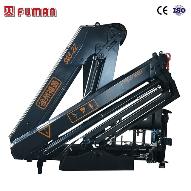
The primary and secondary boom lengths of the folding boom crane determine its base geometry. Hydraulic extensions, the telescoping sections within the knuckle boom, determine the maximum horizontal reach. More extensions mean more reach, but they also mean more dead weight.
Hydraulic pressure relief settings and flow rates affect performance. They limit the ability to extend or retract heavy loads at maximum radius. The dead weight of additional extensions also reduces available lifting capacity at the furthest reach points. A six-extension boom will lift less at 20 feet than a four-extension boom at the same distance because the crane is lifting its own steel.
Primary boom length sets the initial height and clearance.
Secondary boom length dictates articulation flexibility.
Hydraulic extensions provide the final horizontal reach.
Boom dead weight subtracts from gross lifting capacity.
Hydraulic flow dictates the speed of extension under load.
Boom Angle and Articulation Geometry
Boom angles directly alter the physics of the lift. A lower boom angle increases the horizontal working radius. However, it also maximizes the overturning moment against the crane base. Operating with the boom completely flat puts the maximum possible stress on the rotation bearing and the truck chassis.
The articulation point allows for unique up-and-over capabilities. This alters the working radius compared to straight telescopic cranes. Operators can navigate obstacles while keeping the load close to the center of gravity. You can lift a pallet of roofing materials over a parapet wall and then extend the secondary boom downward, maintaining a tight radius.
Jib Attachments and Load Forces
Fly jibs extend the working radius and help access confined spaces. Different boom angles on the jib relative to the main boom alter structural forces. They create varying tensile and compressive stresses on the knuckle joint. A jib is not just extra reach; it is a complex lever arm acting on the main boom.
Operating a jib at a steep or negative angle impacts tipping load limits. It changes the load distribution across the entire structure. Operators must account for these shifts to maintain the overall capacity of the equipment. When you articulate a jib downward, you shift the center of gravity rapidly, which can destabilize the truck if not planned correctly.
The Load Chart: The Ultimate Limiting Factor
Translating manufacturer specifications into real-world operational limits requires mastering the load chart. It serves as the definitive guide for safe operations. You cannot guess capacities; you must read the chart for every single lift.
Cross-Referencing Weight and Distance
A strict inverse relationship exists between weight and distance. As the working radius increases, the maximum allowable load weight decreases exponentially. Reading a load chart involves identifying specific zones where capacity drops off sharply. You will notice that capacity does not decrease linearly; it drops in steps based on which hydraulic extension is deployed.
Operators must pinpoint the exact intersection of load weight and required radius. Failing to respect these boundaries leads to structural failure or tipping. If the chart says 4,200 lbs at 25 feet, lifting 4,500 lbs at 25 feet is a direct violation of safety protocols and risks catastrophic equipment damage.
Configuration Coding and Pre-Lift Audits
Identifying the exact crane configuration prior to calculating radius limits is a safety-critical step. You must account for active boom sections, manual pull-outs, and jib attachments. A crane with a jib attached uses a completely different load chart than the same crane without the jib.
Modern digital Load Moment Indicator systems require precise inputs. The operator must enter specific configuration codes. This ensures the system cross-references the correct load chart for the current setup. Entering the wrong code allows the crane to operate outside its structural limits, bypassing safety lockouts.
Verify the physical configuration of the boom and jib.
Input the corresponding configuration code into the LMI.
Confirm the LMI displays the correct maximum capacity for the setup.
Perform a dry run of the lift to check radius readings on the display.
Compare the LMI radius reading with the physical load chart.
The Impact of Attachments on the Load Chart
Attachments like grapples, rotators, winches, and forks add dead weight to the boom tip. You must deduct this weight from the gross capacity. The load chart assumes a bare hook unless specified otherwise.
Subtracting attachment weight reveals the net capacity at a specific working radius. Ignoring this deduction overloads the crane, especially at maximum extension. If your rotator and grapple weigh 800 lbs, and your chart capacity at 30 feet is 2,000 lbs, you can only lift 1,200 lbs of actual material.
Chassis Matching and Outrigger Stability
A crane is only as capable as the platform it is mounted on. A high-capacity unit on an inadequate truck will suffer a severely restricted working radius. You cannot bolt a massive crane to a light-duty truck and expect it to perform to the load chart.
Gross Vehicle Weight (GVW) and Axle Ratings
Matching a truck mounted knuckle boom crane to a chassis with the correct GVW and axle spacing is mandatory. The chassis weight acts as the primary counterweight. The heavier the truck, the more stable the platform.
This counterweight directly influences the safe working radius. Insufficient chassis weight leads to instability long before the boom reaches its structural limits. If the truck lifts off the ground before the hydraulic relief valve trips, the chassis is undersized for the crane's capacity at that radius.
Chassis Factor | Impact on Stability | Result on Working Radius |
|---|---|---|
High GVW | Provides massive counterweight against overturning moment. | Allows full use of the load chart at maximum radius. |
Low GVW | Insufficient counterweight; truck tips easily. | Severely restricts working radius; requires heavy derating. |
Long Wheelbase | Spreads the load over a larger footprint. | Improves stability over the front and rear sectors. |
Torsionally Stiff Frame | Resists twisting under heavy side loads. | Maintains outrigger contact and prevents sudden shifts. |
Outrigger Spread and Ground Bearing Pressure
The width of the outrigger deployment defines the tipping axis. A wider outrigger spread allows the crane to utilize its maximum working radius safely. The outriggers create a stable square or rectangle; lifting outside this footprint relies entirely on the truck's weight.
Short-rigging, or partially deploying outriggers, restricts stability. Modern crane control systems automatically restrict the working radius when outriggers are not fully extended. Ground bearing pressure must also remain within safe limits to prevent sinking. If an outrigger pad sinks into soft soil during a lift, the crane tilts, the radius increases instantly, and the equipment can roll over.
Environmental and Dynamic Variables
Real-world conditions alter the theoretical working radius. They introduce operational hazards that operators must mitigate on site. A lift that is perfectly safe inside a warehouse might be extremely dangerous outdoors in poor weather.
Operating in Mountainous or Uneven Terrain
Operating on inclines presents severe risks. This is common in specialized applications like crane-assisted tree removal in mountainous areas. An unlevel chassis shifts the center of gravity before you even pick up a load.
This shift effectively increases the working radius on the downhill side. It drastically reduces safety margins. Level-sensing indicator systems, tilt alarms, and chassis leveling jacks are critical to ensure stability before commencing lifts. If your truck is out of level by just a few degrees, a 30-foot radius lift acts like a 35-foot radius lift on the downhill swing.
Dynamic Forces: Wind, Swing Speed, and Transient Loading
Dynamic forces impact the load's center of gravity. Displacement, velocity, and acceleration during slewing shift the load outward. Sudden tensioning of the hoisting line or rapid acceleration creates dynamic amplification factors. You must control the load, not just lift it.
These factors momentarily increase the effective weight at a given radius. Offshore and marine applications require severe derating of the working radius due to wave action and vessel roll. Utilizing smooth hydraulic controls and limiting swing speed prevents load swing, which artificially extends the working radius. If you swing too fast and stop suddenly, the load keeps moving outward, increasing the radius and potentially tipping the truck.
Limit swing speed to prevent outward load drift.
Use smooth hydraulic inputs to avoid shock loading.
Derate capacity charts for high wind conditions.
Account for dynamic amplification during rapid hoisting.
Keep the load as close to the ground as possible during slewing.
Conclusion
Audit your typical job sites to determine the most common setup distances and required reach before purchasing equipment.
Calculate the net capacity required by deducting the weight of all necessary attachments from the gross load chart.
Verify that your chosen truck chassis provides adequate GVW and outrigger spread to support the crane's maximum radius.
Implement strict pre-lift protocols that account for boom deflection and dynamic load shifts.
FAQ
Q: What is the difference between theoretical reach and practical working radius?
A: Theoretical reach is the maximum physical extension of the boom without a load. Practical working radius is the horizontal distance from the center of rotation to the load's center of gravity while under tension, factoring in boom deflection.
Q: How does boom deflection affect the working radius?
A: When lifting heavy loads, the boom flexes downward. This deflection pushes the load further away from the center of rotation, slightly increasing the actual working radius and potentially reducing safe lifting capacity.
Q: Why does lifting capacity decrease as the working radius increases?
A: As the load moves further from the crane's center of rotation, it creates a larger overturning moment. The crane's structural limits and the chassis's counterweight dictate that less weight can be safely supported at greater distances.
Q: How do outriggers impact the maximum working radius?
A: Outriggers define the crane's tipping axis. A wider, fully deployed outrigger spread maximizes stability, allowing the operator to safely utilize the crane's full working radius without risking a rollover.
Q: Does adding a jib increase the crane's lifting capacity?
A: No. While a jib extends the working radius and provides better access to confined spaces, it adds dead weight to the boom tip. This significantly reduces the maximum lifting capacity at the extremity.
Q: How does operating on an incline affect the working radius?
A: An unlevel chassis shifts the equipment's center of gravity. This effectively increases the working radius on the downhill side, drastically reducing safety margins and requiring immediate capacity derating.


