


Which Hydraulic Specifications Matter When Selecting a Knuckle Boom Crane?
Views: 0 Author: Site Editor Publish Time: 2026-07-27 Origin: Site


The true performance bottleneck of any lifting equipment is rarely the steel structure; it is the hydraulic architecture powering it. Fleet managers and procurement teams often base purchasing decisions solely on maximum lifting capacity, overlooking the underlying hydraulic specifications. Misjudging hydraulic pressure, flow rates, or valve configurations leads to sluggish operation, system overheating during high duty cycles, and premature component failure.
Selecting the right equipment requires translating operational demands into specific hydraulic requirements. This guide breaks down the critical hydraulic specifications to evaluate when shortlisting a knuckle boom crane, ensuring alignment between chassis capabilities, lifting requirements, and long-term reliability.
Pressure vs. Longevity: High-pressure hydraulic systems offer greater lifting capacity with smaller, lighter cylinders, but low-pressure systems generally experience less component stress, lowering long-term maintenance costs.
Flow Rate Dictates Speed: The hydraulic flow rate (GPM/LPM) directly determines the operational speed of the crane; however, mismatched flow rates and pump types (gear vs. piston) cause severe thermal inefficiencies.
Valve Architecture is Critical: Precision lifting requires proportional control valves, while standard applications may only require manual bi-directional valve blocks. The choice impacts both operator control and upfront cost.
Integration Matters: For a truck mounted knuckle boom crane, the hydraulic system must perfectly align with the vehicle's Power Take-Off (PTO) capabilities and payload weight limits.
The Role of Hydraulics in Knuckle Boom Crane Performance
Establish the baseline operational requirements before looking at specific models. You need to know the frequency of lifts, required precision, and environmental operating conditions. A crane working in freezing temperatures requires different fluid viscosity and seal materials than one operating in a desert environment. Duty cycle dictates everything. If operators run the crane continuously for eight hours a day, the hydraulic system must handle sustained heat generation without degrading fluid properties.
Contrast the hydraulic demands of a stiff boom crane with a folding boom crane. Stiff boom cranes rely primarily on a single hydraulic winch motor to lift loads vertically. The hydraulic circuit is relatively straightforward. Folding boom cranes require a complex, multi-cylinder system to manage structural articulation, folding, and extension. Operators frequently actuate three or four functions simultaneously. These differing mechanics alter the necessary flow distribution and pressure management across multiple simultaneous crane functions.
Hydraulic pressure acting on cylinder bore sizes dictates the crane's lifting moment. Evaluating maximum capacity at maximum horizontal reach provides a more accurate test of hydraulic capability than static close-range lifting. When the boom is fully extended horizontally, the leverage exerts maximum force on the main lift cylinder. If the hydraulic pressure drops even slightly, the load will sag. The relationship between hydraulic fluid volume, flow rate, and the crane's ability to perform continuous operations dictates whether the system will overheat or experience pressure drops during heavy use.
Field experience shows that undersized hydraulic lines restrict flow, causing fluid velocity to spike. High fluid velocity generates friction, which manifests as heat. Heat destroys hydraulic seals and reduces the lubricating properties of the oil. Proper system design matches hose diameters to the pump's maximum output, ensuring smooth, unrestricted flow to the valve bank and cylinders.
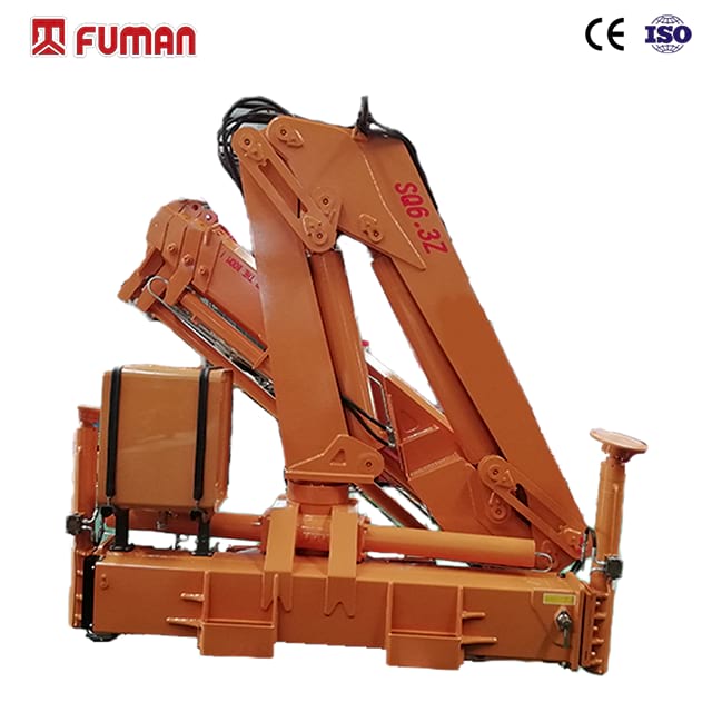
Core Hydraulic Specifications to Evaluate
Operating Pressure: High-Pressure vs. Low-Pressure Systems
High-pressure architectures operate in the 4,000 to 5,000 PSI range. They offer reduced component size, lower weight, and higher immediate lifting force. Smaller cylinders mean a lighter crane, which preserves truck payload capacity. However, they face increased wear on seals, higher susceptibility to fluid contamination, and stricter maintenance intervals. High pressure forces fluid through microscopic imperfections in seals, leading to weeping and eventual failure if not meticulously maintained.
Low-pressure architectures operate around 2,500 to 3,000 PSI. They provide extended component life, easier maintenance, and better heat dissipation. The trade-off is that they require larger, heavier cylinders that may impact payload. Municipal fleet buyers often specify lower operating pressures to reduce the occurrence of micro-pinhole leaks and extend service life. The larger fluid volume in low-pressure systems acts as a heat sink, keeping operating temperatures manageable during long shifts.
Specification | High-Pressure Systems (4000+ PSI) | Low-Pressure Systems (<3000 PSI) |
|---|---|---|
Component Size | Compact and lightweight | Bulky and heavy |
Payload Impact | Minimal reduction in truck payload | Noticeable reduction in truck payload |
Seal Wear | Accelerated wear, requires frequent checks | Extended lifespan, lower stress |
Heat Generation | High, often requires active cooling | Moderate, better natural dissipation |
Flow Rate (GPM/LPM) and Pump Selection
Fixed displacement gear pumps are cost-effective and reliable in standard, intermittent-use applications. They deliver a constant volume of fluid per revolution, regardless of system pressure. They have limitations in flow control and energy efficiency. When the crane is not moving, the fluid simply bypasses back to the tank through a relief valve, generating unnecessary heat and wasting fuel.
Variable displacement piston pumps offer strong returns for high-demand applications. They adjust flow based on load demand, reducing heat generation and parasitic load on the truck engine. If the operator only moves a joystick slightly, the pump destrokes, delivering only the required fluid. This efficiency translates to lower fuel consumption and significantly cooler hydraulic oil temperatures during continuous operation.
Control Valve Architecture and Precision
Manual hydraulic control valve blocks contrast with electro-hydraulic proportional valves. Standard technical specifications require a minimum of four bi-directional valves for basic functions. Manual valves are binary; they are either open or closed. This makes feathering a load difficult. Electro-hydraulic proportional valves allow for simultaneous, multi-function movements without pressure loss. The spool inside the valve shifts proportionally to the electrical signal from the remote control, metering the fluid precisely.
Specifying manual and proportional blocks equipped with individual, circuit-specific work port relief valves is a mechanical necessity. These valves protect individual crane functions from localized structural overloads. If a load shifts suddenly, causing a pressure spike in the swing circuit, the work port relief valve vents the excess pressure back to the tank, preventing a blown hose or bent cylinder rod.
Load-sensing directional valves communicate with variable displacement pumps to provide exact fluid requirements. A signal line runs from the valve bank to the pump compensator. When the operator demands movement, the valve sends a pressure signal to the pump, telling it exactly how much flow to produce. This optimizes fuel consumption and control precision, eliminating the heat generated by dumping excess flow over a main relief valve.
Sizing Hydraulics for a Truck Mounted Knuckle Boom Crane
PTO (Power Take-Off) Compatibility and Chassis Integration
Matching the hydraulic pump's torque and RPM requirements to the truck transmission's PTO output is critical. You cannot simply bolt any pump to any transmission. The PTO gear ratio determines the pump speed relative to engine RPM. If the pump spins too fast, it will cavitate, destroying internal components. If it spins too slowly, the crane will operate sluggishly.
The physical footprint of hydraulic reservoirs and pumps on the truck chassis impacts the installation of the crane base. Frame rail space is always at a premium. You must account for fuel tanks, exhaust aftertreatment systems, and toolboxes. Careful planning around space and mounting constraints ensures the hydraulic reservoir sits close enough to the pump to prevent suction line restriction.
Calculate the required pump flow based on the crane manufacturer's specifications.
Determine the optimal engine RPM for crane operation (usually between 900 and 1200 RPM).
Select a PTO gear ratio that spins the pump at the correct speed at the target engine RPM.
Verify the transmission PTO gear can handle the maximum torque required by the pump at full pressure.
Route suction and pressure lines away from exhaust heat sources and sharp frame edges.
Weight Trade-offs: Payload Capacity vs. Hydraulic Components
The weight of hydraulic fluid, oversized reservoirs, and heavy low-pressure cylinders subtracts from the vehicle's legal payload capacity. Every gallon of hydraulic oil weighs roughly 7.2 pounds. A 100-gallon reservoir adds over 700 pounds to the chassis before factoring in the weight of the steel tank itself.
Balancing hydraulic robustness with the need to maximize commercial payload requires strategic component selection. You might opt for a smaller reservoir paired with a high-efficiency oil cooler to maintain fluid temperature without carrying excess oil weight. Using high-tensile steel for the crane structure offsets the weight of heavier low-pressure hydraulic cylinders.
Advanced Hydraulic Features for Folding Boom Cranes
Hydraulic Winch Integration and Auxiliary Lines
Integrating a winch on a folding boom crane to achieve stiff-boom style hoisting requires specific valve sections. You need dedicated flow requirements for line speed and counterbalance valves for load holding. The winch motor demands continuous flow, which can starve other functions if the pump is undersized. Counterbalance valves lock the fluid in the motor when the control valve is centered, preventing the load from free-falling.
Routing auxiliary hydraulic lines to the boom tip is necessary for powering attachments like rotators, grapples, or augers. These lines must articulate with the boom sections without kinking or stretching. Hose reels or internal routing through the boom profile protect these vulnerable lines from snagging on branches or building materials during operation.
Thermal Management: Hydraulic Oil Coolers
Continuous operation, high ambient temperatures, and flow restrictions generate heat that degrades hydraulic fluid viscosity and damages seals. When oil gets too hot, it thins out, reducing its ability to lubricate moving parts. This leads to metal-on-metal contact inside the pump and cylinders.
Specifying an active hydraulic oil cooler maintains optimal operating temperatures during heavy duty cycles. Fan-driven heat exchangers mount on the return line, pulling ambient air across a radiator core to extract heat from the oil before it enters the reservoir. Thermostatic switches automatically engage the fan only when the oil reaches a specific temperature, reducing electrical draw on the truck's alternator.
Electronic Load Moment Indicators (LMI) and Overload Protection
Modern LMIs interface with hydraulic pressure transducers on the main lift cylinder to calculate load moments in real-time. The transducer measures the exact pressure required to hold the load. The LMI computer compares this pressure against the boom's current angle and extension length to determine the percentage of maximum capacity.
Hydraulic dump valves automatically halt boom extension or lowering functions when maximum capacity is reached. If the operator attempts to lift a load that exceeds the chart, the LMI cuts the electrical signal to the dump valve. The valve opens, venting pilot pressure and neutralizing the control levers. This ensures compliance with lifting regulations and prevents catastrophic structural failure.
Assessing Long-Term Value and Maintenance Risks
Filtration Systems and Contamination Control
High-quality return-line and pressure-line filters protect sensitive proportional valves and piston pumps from particulate damage. Hydraulic systems fail primarily due to contamination. Dirt entering through breather caps or worn wiper seals acts like sandpaper on internal components. Pressure filters catch debris immediately after the pump, while return filters clean the oil before it re-enters the tank.
Integrated diagnostic ports are essential for routine hydraulic fluid analysis. Mechanics connect pressure gauges to these ports to troubleshoot circuit issues without cracking lines and introducing air or dirt into the system. Fluid sampling ports allow technicians to draw oil samples for lab analysis, identifying wear metals before a component fails completely.
Hose Routing, Wear Points, and Replacement Accessibility
Routing hydraulic hoses internally through the boom sections offers protective benefits against external impacts. However, internal routing complicates maintenance. Replacing a blown internal hose often requires disassembling boom sections. External routing provides ease of maintenance, allowing mechanics to swap hoses in minutes on the job site.
Specifying protective hose sleeves and hard-piping in high-wear articulation zones improves abrasion resistance. Nylon burst sleeves protect operators from high-pressure fluid injection injuries if a hose fails near the control station. Steel tubing dissipates heat better than rubber hoses and eliminates flexing in straight runs along the boom.
Warranty Coverage on Hydraulic Components
Scrutinize warranty documentation specifically regarding hydraulic cylinders, pumps, and valve blocks. Manufacturers often exclude failures related to fluid contamination or improper PTO engagement. Ensure the warranty covers both parts and labor for replacing major hydraulic components. Document all filter changes and fluid analyses to maintain warranty validity.
Conclusion
Request detailed hydraulic schematics and capacity charts from manufacturers to verify flow rates and pressure ratings.
Consult a specialized upfitter to confirm PTO torque limits and chassis frame space before purchasing the crane.
Specify variable displacement pumps and proportional valves if your operators require precise, multi-function control.
Install an active hydraulic oil cooler if the equipment will run continuous duty cycles in hot climates.
FAQ
Q: What is the difference between a high-pressure and low-pressure knuckle boom crane?
A: High-pressure systems use smaller cylinders and save weight but cause more wear on seals. Low-pressure systems use larger, heavier cylinders but reduce component stress, lowering lifetime maintenance expenses and minimizing pinhole leaks.
Q: How does hydraulic flow rate affect crane operation?
A: The hydraulic flow rate, measured in GPM or LPM, directly dictates the speed of boom extension, rotation, and lifting functions. Higher flow rates enable faster operation but require proper thermal management to prevent overheating.
Q: Do I need a variable displacement pump for my truck mounted knuckle boom crane?
A: Variable displacement piston pumps are ideal for continuous duty cycles and fuel efficiency because they adjust flow to demand. Gear pumps are sufficient and cost-effective for intermittent use.
Q: What are proportional hydraulic valves?
A: Proportional valves allow operators to control the speed of crane movements based on how far the lever is engaged, enabling precise, simultaneous multi-function operations without sudden pressure drops.
Q: Why are work port relief valves necessary?
A: Work port relief valves protect individual crane functions, such as the swing or boom extension, from localized structural overloads by venting excess pressure before mechanical damage occurs.


